BRIDGE DESIGN
MANUAL
Miscellaneous Design Miscellaneous
Highway Structures Design
8.3.4 Bridge Approach Slabs
A.
General
Bridge
approaches typically experience two types of settlement, global and local.
Global settlement consists of a consolidation of the underlying natural
foundation soils, and is evidence of possible long-term differential settlement
between the bridge structure and the bridge embankment.
Local settlement consists of compression of fill materials directly
beneath the approach pavement, and is evidence of possible embankment
consolidation within the upper 10 to 20 feet of the bridge embankment.
It is the combination of global and local settlements adjacent to the
bridge end piers that forms the characteristic “bump” in the pavement at the
bridge ends. The purpose of the
bridge approach slab is to significantly reduce local settlement and to
accommodate global settlement by providing a gradual transition between the
roadway and the bridge deck.
Bridge
approach slabs are required for
all new and widened bridges, except when concurrence is reached between the
Materials Laboratory Geotechnical Branch, the Region Design Project Engineer
Office, and the Bridge and Structures Office, that approach slabs are not
appropriate for a particular site. In
accordance with WSDOT Design Manual Chapter 1120, the State Geotechnical
Engineer will include a recommendation in the geotechnical report for a bridge
on whether or not bridge approach slabs should be used at the bridge site.
Factors considered while evaluating the need for bridge approach slabs
include the amount of expected settlement and the type of bridge structure.
B.
Bridge Preliminary Plan
All bridge
preliminary plans shall show approach slabs at the ends of the bridges.
In the Notes to Region in the first submittal of the Preliminary Plan to
the Region, the designer shall ask the following questions:
1.
Bridge approach slabs are shown for this bridge, and will be included in
the Bridge PS&E. Do you concur?
2.
The approach ends of the bridge approach slabs are shown (a) parallel to
the back of pavement seat (b) normal to the survey line (the designer shall
propose one alternative).
Do you
concur?
3.
Please indicate the pavement type for the approach roadway.
Depending on
the type and number of other roadway features present at the bridge site (such
as approach curbs and barriers, drainage structures, sidewalks, utilities and
conduit pipes) or special construction requirements such as staged construction,
other questions in the Notes to Region pertaining to the bridge approach slabs
may be appropriate.
Special
design conditions exist when the skew of the bridge pavement seat is greater
than 30 degrees, and for wide roadway widths (including bridge widenings with or
without existing bridge approach slabs). The
preliminary plan shall include details showing how these conditions are being
addressed for the bridge approach slabs, and the designer shall include
appropriate questions in the Notes to Region asking for concurrence with the
proposed design.
BRIDGE DESIGN
MANUAL
Miscellaneous Design
Miscellaneous Highway Structures Design
C.
Bridge Approach Slab Design Criteria
The current
standard plan for bridge approach slabs is based upon the following design
criteria:
1.
The bridge approach slab is designed as a slab in accordance with Section
4.6 of the AASHTO LRFD Bridge Design Specifications – U.S. Units, Second
Edition 1998
and current interims (Strength I loading, IM = 1.3, no skew).
2.
The end support is assumed to be a uniform soil reaction with a bearing
length that is approximately 1/3 the length of the approach slab (25/3 = 8
feet).
3.
The Effective Span Length (Seff) is assumed to be:
25 feet
- (25 feet/3)/2
- 10 inches
= 20 feet
4.
Longitudinal steel reinforcing bars do not require modification for
skewed applications.
5.
See Bridge Design Manual Section 9.3.2 for a slab reaction applied to the
pavement seat that assumes Seff = 20’-0”.
6.
The maximum skew accommodated by the standard design is 30 degrees.
Design
circumstances that vary from the above design criteria may require revisions to
the details shown in the standard plan.
D.
Bridge Approach Slab Details in Bridge Plans
The bridge
approach slab shall be shown in the PLAN view of the LAYOUT sheet.
The set of Bridge Sheets shall also include the two sheets of approach
slab details (Bridge Design Manual Detail Sheets 8.3-A13 and 8.3-A14), modified
as appropriate to match the site conditions of the bridge.
Additional details to address special roadway features and construction
requirements (such as approach curbs and barriers, drainage structures,
sidewalks, utilities and conduit pipes, stage construction, wide roadway width,
and skew greater than 30 degrees) should also be included.
Bridges for
local agency projects may reference Standard Plan A-2 in place of Bridge Design
Manual Detail Sheets 8.3-A13 and 8.3-A14.
The bridge
approach slab width shall be curb to curb of the outside bridge barriers
(traffic barrier or pedestrian barrier). This
means, if sidewalks and interior barriers (such as traffic-pedestrian barriers)
are present, special details will be required in the Bridge Sheets to show how
the sidewalks and interior barriers are connected to and constructed upon the
bridge approach slab.
BRIDGE DESIGN
MANUAL
Miscellaneous Design
Miscellaneous Highway Structures Design
Approach
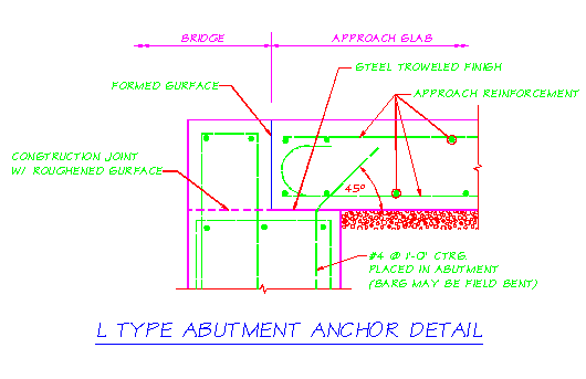
slab anchors installed at bridge abutments shall be shown in the Bridge Sheets.
For bridges with semi-integral type abutments, this can be accomplished
by showing the approach slab anchors in the End Diaphragm or Pavement Seat
details. For bridges with L type
abutments, this requires adding the detail shown below to the end pier Bridge
Sheets. The approach slab anchor
for bridges with L type abutments shall be a #4 bar at one foot spacing, bent as
shown, with 1’-0” embedment into both the pier and the bridge approach slab.
This bar shall be included in the bar list for the bridge substructure.

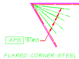
For
bridges with skews greater than 30 degrees, the approach end of the bridge
approach slab shall be normal to the roadway centerline. Also
for bridges with skews greater than 30 degrees, additional steel reinforcing
bars shall be added to the acute corners of the bridge approach slabs, as shown
in the detail below. The flared
corner steel shall be 10 feet long, epoxy coated, and placed on top of the top
layer of steel.
6. Precast
Approach Slabs:
Precast
approach slabs greatly simplify the construction. 10°
is the maximum skew that may be used with precast approach panels.
This limits the effects of having multiple acute angles in the traveled
lanes.
 Bridge approach slabs for skewed bridges of
significant width (three lanes or more) may have the approach end of the bridge
approach slab stepped or staggered to reduce the size of the slab or to
accommodate stage construction.
Semi-integral
type abutments should not be designed for contributory expansion lengths greater
than 200 feet (point of fixity to joint) because large expansion movements and
highly skewed joints may require compression seals larger than the 2-1/2 inch
compression seal shown on the Standard Plan.
See Bridge Design Manual Section 8.4.1.
Bridge deck
surface drainage shall be carried off and collected beyond the bridge approach
slab. Drainage structures such as
grate inlets and catch basins shall be located in accordance with Standard Plan
A-4 and the recommendations of the Hydraulics Office. If bridge deck surface drainage must be collected at the back
of pavement seat, the drainage structure shall be a bridge grate inlet (See
Bridge Design Manual Detail Sheet 8.4-A4).
BRIDGE DESIGN
MANUAL
Miscellaneous
Design
Miscellaneous Highway Structures Design
All costs in
connection with constructing bridge approach slabs are included in the unit
contract price per square yard for “Bridge Approach Slab”, including steel
reinforcing bars, approach slab anchors, concrete, and compression seals.
For the Contractor’s information, the total quantity of epoxy-coated
and plain steel reinforcing bars shall be listed in the bar list sheet for each
bridge.
E.
Bridge Approach Slabs for Bridge Widenings
Adding
bridge approach slabs to existing bridges that are being widened may require
modifications of the existing bridge ends.
When the existing bridge end does not provide sufficient support shelf
length (ten inches minimum) any existing substandard pavement seat shall be
removed, and a replacement pavement seat shall be constructed. The Bridge Design Engineer on a site-specific basis may
modify this requirement. Pavement
seat details conforming to Bridge Design Manual Detail Sheet 8.3-A15 shall be
added to the Bridge Sheets.


 Bridge approach slabs for skewed bridges of
significant width (three lanes or more) may have the approach end of the bridge
approach slab stepped or staggered to reduce the size of the slab or to
accommodate stage construction.